Mission Statement
Access propulsion research as undergraduates by developing a custom valved pulsejet engine and testing framework, characterized with modern tools and methods.

Access propulsion research as undergraduates by developing a custom valved pulsejet engine and testing framework, characterized with modern tools and methods.
Establish remote engine operation
Characterize the engine
Analyze the pulsed combustion cycle
With enough fuel and air in the chamber, combustion occurs, closing the reed valve and stopping air from entering.
Hot gases are expelled through the converging section and out the exhaust tube; gas momentum lowers the chamber pressure
With the chamber pressure below atmospheric, the reed valves lift open to admit fresh air; some hot gas is also drawn in
Fuel is injected alongside air. Hot gases return to the combustion chamber, ready to re-ignite the system.


The pulsejet was fully designed by the Yale capstone team. All parts of the pulsejet were manufactured on campus from sheet metal, except for the tube and cone stock. The team thanks Yale Wright Lab, Nick Bernardo, and the CEID for their assistance in manufacturing.
Featured assemblies are detailed below.
Guides air from the forced air startup system and the environment into the valve assembly.
The duct is made of four panels that were waterjetted as flat-packed blanks of 22-gauge mild steel. Each panel was then stamped with 3D-printed dies that accounted for material springback. The panels, plus a mounting interface on either side, were TIG-welded together.
Designed by Jonah Halperin


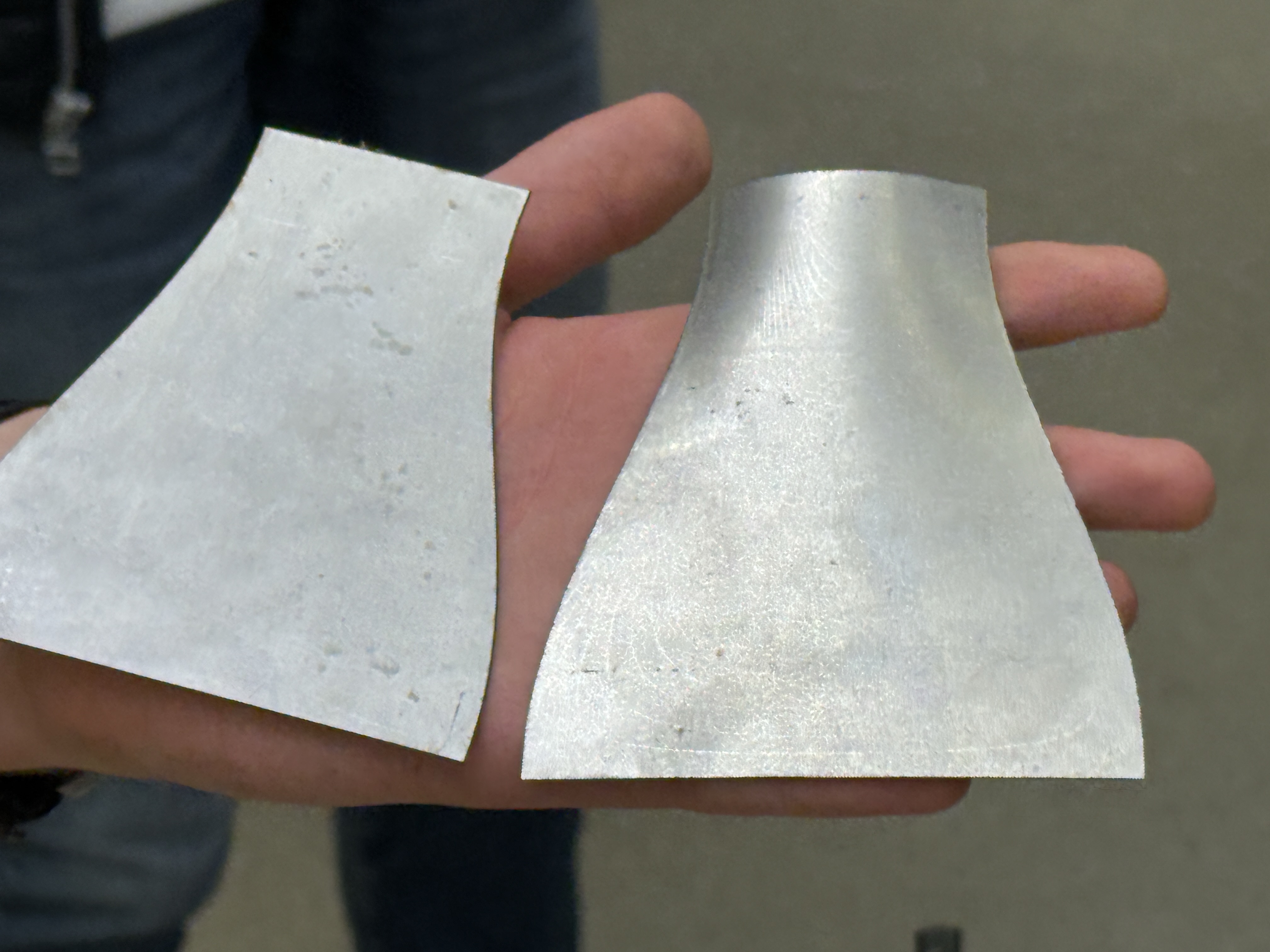

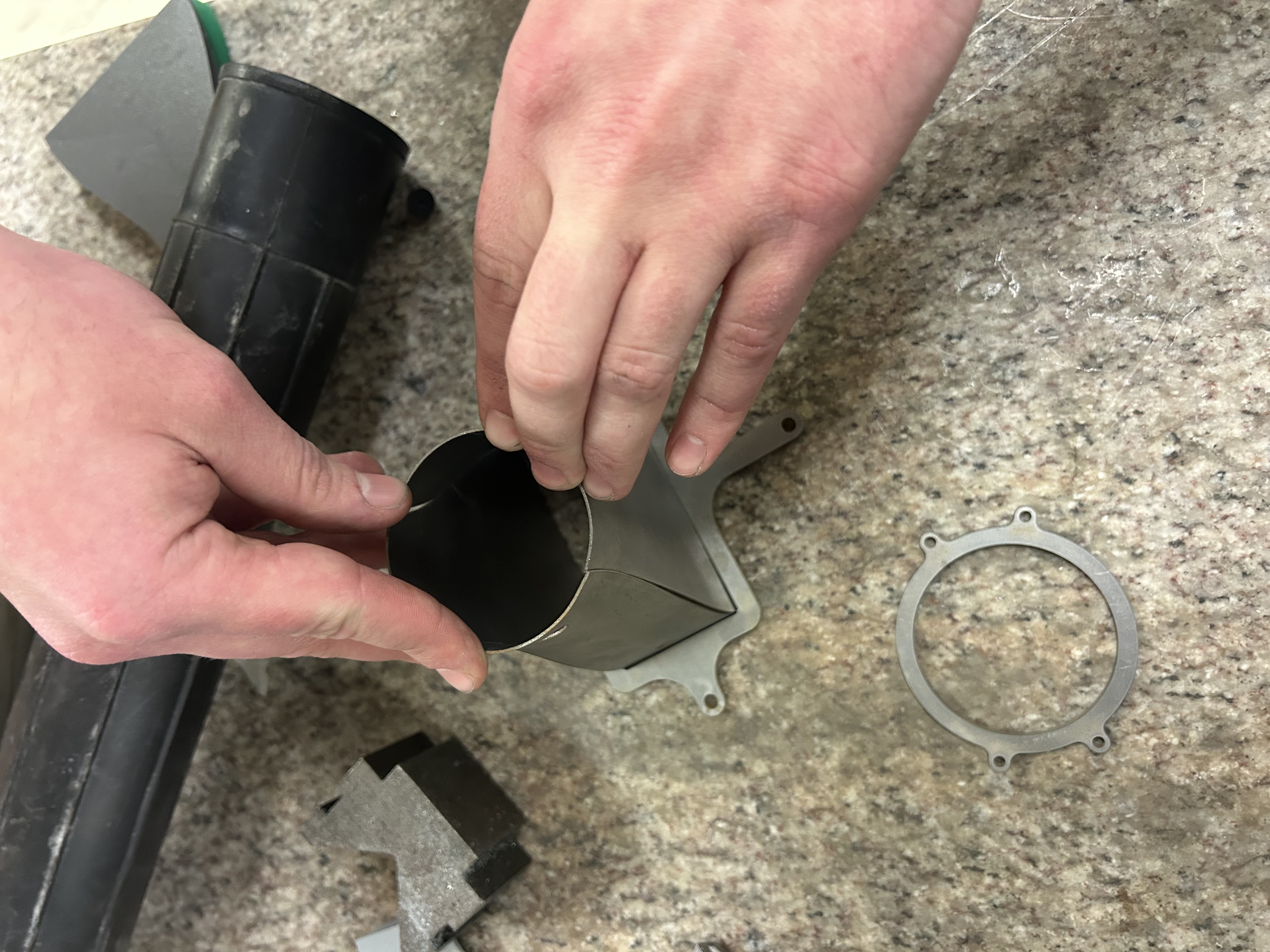
The orange colors are the dies. Red is the shape that is formed by the dies. Green is the ideal shape that the part returns to after springback.
The reed valve assembly houses thin metal flaps called reeds that deflect open due to airflow, but slam shut from combustion pressure. When the exhaust gases leave the combustion chamber, the pressure in the chamber falls below atmospheric, allowing for the reeds to be open again to intake more air for the next cycle.
Designed by Jonah Halperin. Prototype assistance from Cayden Cerveny.

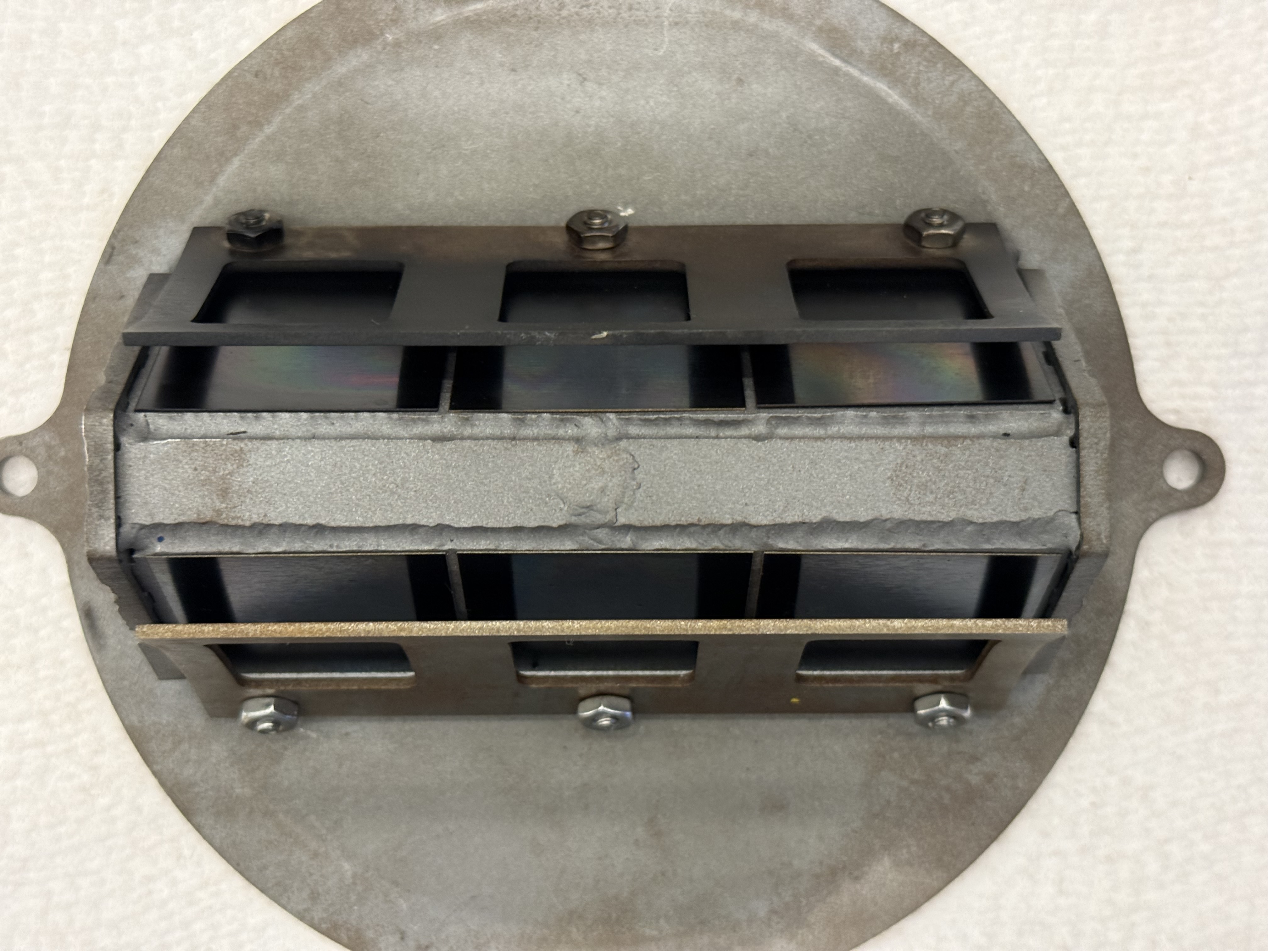


The airflow through the reed valve was confirmed by anemometer testing
The system has a hard-wired, fail-safe remote power and control system. A remote switch box controls the system power, enabling remote control of the fuel, air, and ignition systems. A DAQ (Data Acquisition System) streams pressure, load, and temperature data to a remote computer at 2500Hz per channel.
Designed by Casimir Hixon. Additional design help by Cayden Cerveny, Aaron Cope, & Jonah Halperin.

The fuel handling system stores and supplies gasoline to the chamber at variable pressure using a pressure regulator. Interchangeable fuel nozzles allow for adjustable atomization and mass flow.
Designed by Casimir Hixon.

The engine casing includes the combustion chamber for ignition, a reducing section that builds pressure, and an exhaust tube whose length sets the system’s resonance and performance.
Sized by Jonah Halperin. Casing designed by Jack Griffin and Casimir Hixon.

The support structures ensure that the system is thermally and physically isolated during the static fire sequence. All parts in contact with the engine are made of steel; otherwise, they are made of aluminum. The system supports a firewall to protect the fluids equiptment.
Designed by Aaron Cope and Jack Griffin.


